Drawing in architectural design
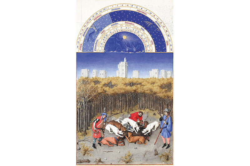
"Architecture has contained all the great ideas of the human race. To every religious symbol, every thought and every thought or thought has been devoted a page in this vast book."
(Victor Hugo)
In the current historical moment, architecture, while retaining its role as a mirror of society, incorporates and is incorporated by the information age, takes place both inside and outside cyberspace, inside real space as well as outside it. Karl Chu argued that if for Corbusier the machine is in the garden (both the lawnmower and the house as a living machine), now the garden is in the machine (any world, including the real world, can be and is simulated by virtual space), and architecture is and will remain the construction of possible worlds.
The way in which the contemporary architectural phenomenon is marked by the digital revolution comes first and foremost through the profession's re-technologization, the shift to new ways of working. Designing almost exclusively "on the computer" has become the norm in architectural design. And if until recently computational architecture proposed the use of the computer only as a tool for drawing, nowadays it even takes on the role of assistant and aid in the design and analysis process. The virtual environment also offers the possibility of bridging the gap between drawing and reality with digital fabrication. Just as the modernists used the latest discoveries of the industrial revolution to divert and change the course of architecture, so computation (the only real and entirely new discovery of the last century - S. Wolfram) is today serving to define a new tool and thus a new aesthetic and approach to architecture.
The use of the computer in the generation of architecture is nowadays done at different levels, although it can be said that the last decade has marked a total shift towards the use of the computer in almost every architectural project. Obviously, the way of working and the degree of digital involvement in the creative and production process differs from firm to firm and from project to project. The four models proposed by James Steele1 are a good exercise in illustrating different ways of working and attaching or correlating them to the final architectural product outcomes. Thus, Steele identifies a first mode where the use of the computer is used as a substitute for the drawing board. Much of contemporary architecture that has been designed on the computer fits here. A second method identified by Steele refers to where the use of the traditional method on sketches and models is accompanied by 3D scanning of the latter and using the digital environment to detail the design more easily2. A third method would be to combine the manual and digital approach. Sketches or layouts similar to the desired solutions are scanned or otherwise entered into the digital space, and then software generates additional solutions. In a fourth and last proposed method, the computer is not a source of inspiration, but the architect basically generates tools (software, algorithms) which in turn produce families of solutions, from which a final one is extracted (by various selection methods). The computer thus participates in the result not through its own creativity and not as a substitute for the architect, but simply as a creative aid used to its maximum capacity.
Design at its various scales calls for different methods and, therefore, families of software with varied roles and functions. Drawing, design, its analysis and representation sometimes involve specific tools. Below are some possible digital tools that are valid and relevant for architectural, urban or object design projects.
On the one hand there are software tools for geometric drawing and modeling. These are applications where three-dimensional solid surfaces and volumes can be modeled and two-dimensional projections can be rendered. They are very relevant in object design. Architectural design also uses them, although they are not specifically designed for architectural design and may pose efficiency problems. In urban planning they are used and effective when the application offers the possibility of georeferencing and sometimes environmental analysis.
The history of CAD systems shows that most of the software developed and used in architecture has been borrowed from other fields (automobile construction, aeronautics, electrical installation design, etc.), with the exception of BIM packages which are specifically designed for architecture. They are based on object-oriented programming and greatly facilitate the architectural design process. Most BIM systems are cumbersome and time-consuming and expensive to use for object design, whereas for urban planning they can be used successfully, but do not necessarily present the most efficient solutions in terms of modeling time-to-memory space ratio.
Rendering replaces freehand perspective drawing and is relevant and used at all scales of architectural design. Rendering softwares are applications that virtually reproduce the effects of the real environment from materials, textures, lights applied and reflected on volumes or surfaces3.
The need to order information as text and images brings special applications to the scene or comes in the form of options (layout) in integrated packages. They are generally intended for digital presentations or printing on flat surfaces. In architecture they are used for editing plans or post-processing renderings. Some architectural techniques use such applications to replace three-dimensional modeling (photo collage technique).
Animation is a sequence of still images (renderings) and has its origins in movie production. With the beginning of the use of animation in architecture or design (in '98, Greg Lynn wrote Animate Form) a fourth dimension, that of time, is introduced and architectural design no longer has to be static, it can simulate evolution like a natural system. When the design is no longer static, but evolutionary and dynamic, it loses that quality that classical or modern architecture had of petrifying a solution.
Softwares for environmental analysis and thermo-technical calculations of the building's energy requirements, as well as optimal orientation, prevailing wind directions and air currents have become increasingly popular with the pressure to respond to sustainability and economic needs. Equally, they can come as individual packages receiving imported files or embedded in other software4. They are extremely useful in urban planning and architectural projects, but less important usually for object design. (...)
Read the full text in issue 1/2014 of Arhitectura Magazine
NOTES:
1 Steele, James - Architecture and computers: action and reaction in the digital design revolution, Laurence King Publishing; London; 2001; p. 65.
2 Here perhaps the best example is the work of Frank Gehry, particularly that of his early creative phase.
3 Rendering applications are included in many CAD applications with NURBs, solid or BIM modeling. V-ray, for example, is a particularly sought-after rendering engine, it can be embedded in most design applications from 3dMax to Revit, Maya, Rhino or Blender, but these engines can also exist as separate applications where the user imports a modeling from another software for rendering (Maxwell, Artlantis).
4 Two often used examples would be Ecotect and Project Vasari from Autodesk, both open-source and coming as stand-alone applications. Ecotect can be plugged into Grasshopper.
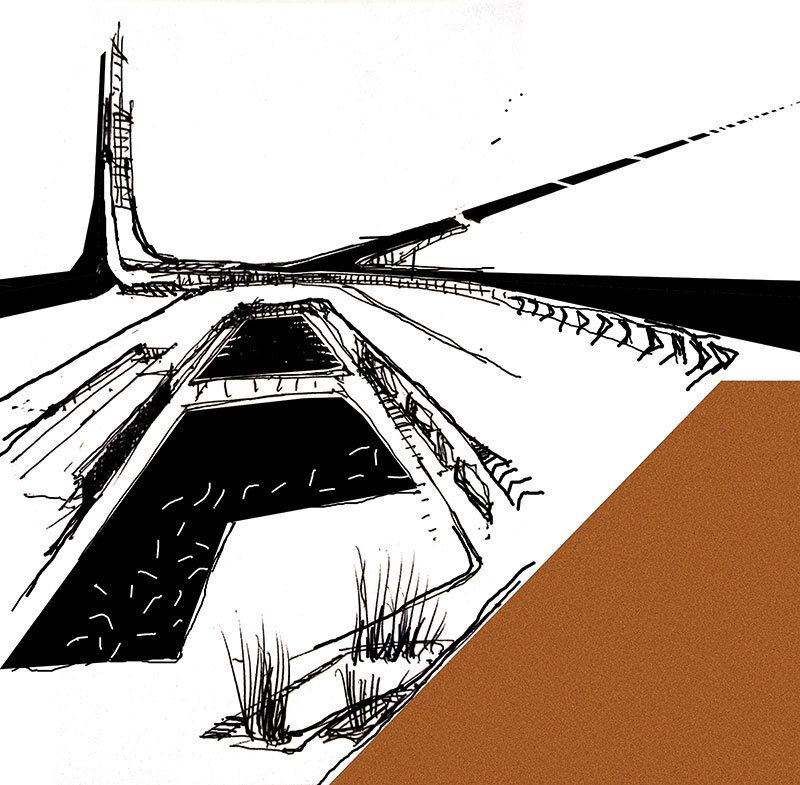
Photo: Evoto rendering - project in the IAAC digital fabrication studio
team: Urte Naujekaide, Joseph Galea, Anca Horvath,tutors: Tomas Diez, Edouard Cabay
Evoto is an exercise project that tries digital mathematical modeling with the idea of creating a tower made of all the studio projects. The lower points, the upper points, the rule of working trigonometrically and the central cylinder are the datum of the theme.
Team: Urte Naujekaide, Joe Galea, Anca Horvath
Supervisors: Edouard Cabay, Thomas Diaz
Technology: three-dimensional printing
Manufacturing time: 90 min.
Volume = 119.853,468(+/-0,0001) cubic mm
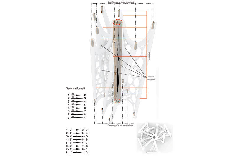
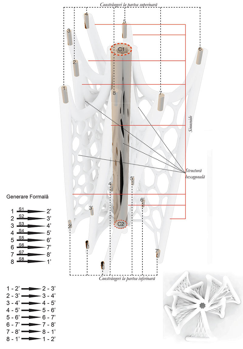
Step 1: Connect the bottom points to the top points trigonometrically, these points are the constraints of the design theme (as in the adjacent diagram),
Step 2: Generate sinusoids between these points. For each sinusoid, there are parameters that control (a) the amplitude of the curve, (b) the number of iterations, and (c) the angle of rotation.
Step 3: Minimum surfaces are generated between the sinusoids.
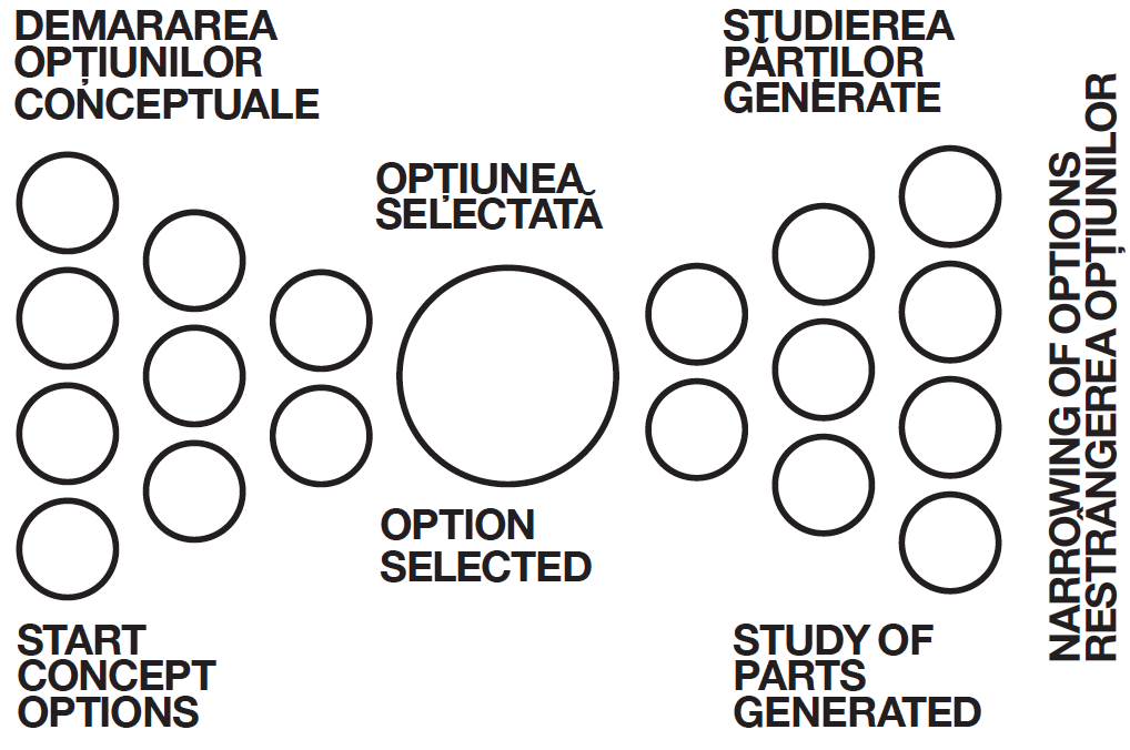
Step 4: The parameters (sliders/variables) of the geometry are then input as genomic values into an evolutionary algorithm (Galapagos, Grasshopper). The fitness function is the area of the minimum area between the sinusoids. The algorithm attempts to minimize this area by modifying the variables between the bounds that define their corresponding number domains. The chosen solution was one of several hundred given by the evolutionary algorithm, both the efficiency factor and the aesthetics were taken into account.
Step 5: The last step was to link the sinusoids and the minimal surfaces generated by the core of the central cylinder (precondition of the design theme). C1 and C2 (the circles defining the central cylinder) were subdivided into 8 equal parts and 8 lines were drawn dividing the cylinder. Each sinusoid is then connected to the nearest line on the cylinder. A minimal surface is again generated between each of these pairs, and a hexagonal texture with rounded vertices is applied to it. The lines defining the hexagonal surface, as well as those defining the sinusoids, are then passed through the pipe function (a pipe of a given diameter is created along the curves). The pipe diameters take into account the material from which the tower is to be printed, the minimum diameter to allow strength was 0.6 mm.